A To D Converter Circuit Diagram . It is an electronic device used for converting an analog signal into a digital signal. adc stands for analog to digital converter. analog to digital converter (adc) is an electronic integrated circuit used to convert the analog signals such as voltages to digital or. we describe here four major circuit architectures used in a/d converter (adc) design and outline the role they play in. Also called the parallel a/d converter, this circuit is the simplest to understand. It is formed of a series of comparators, each.
from userfixfrey.z19.web.core.windows.net
analog to digital converter (adc) is an electronic integrated circuit used to convert the analog signals such as voltages to digital or. adc stands for analog to digital converter. Also called the parallel a/d converter, this circuit is the simplest to understand. It is an electronic device used for converting an analog signal into a digital signal. It is formed of a series of comparators, each. we describe here four major circuit architectures used in a/d converter (adc) design and outline the role they play in.
Simple Ac To Dc Converter Circuit Diagram
A To D Converter Circuit Diagram It is an electronic device used for converting an analog signal into a digital signal. adc stands for analog to digital converter. It is formed of a series of comparators, each. analog to digital converter (adc) is an electronic integrated circuit used to convert the analog signals such as voltages to digital or. we describe here four major circuit architectures used in a/d converter (adc) design and outline the role they play in. It is an electronic device used for converting an analog signal into a digital signal. Also called the parallel a/d converter, this circuit is the simplest to understand.
From www.researchgate.net
Schematic of an A/D converter. Download Scientific Diagram A To D Converter Circuit Diagram adc stands for analog to digital converter. It is an electronic device used for converting an analog signal into a digital signal. analog to digital converter (adc) is an electronic integrated circuit used to convert the analog signals such as voltages to digital or. Also called the parallel a/d converter, this circuit is the simplest to understand. . A To D Converter Circuit Diagram.
From guidefixsextaneruf.z4.web.core.windows.net
A/d Converter Circuit Diagram A To D Converter Circuit Diagram Also called the parallel a/d converter, this circuit is the simplest to understand. adc stands for analog to digital converter. we describe here four major circuit architectures used in a/d converter (adc) design and outline the role they play in. analog to digital converter (adc) is an electronic integrated circuit used to convert the analog signals such. A To D Converter Circuit Diagram.
From manualwiringtraci.z19.web.core.windows.net
Simple A D Converter Circuit Diagram A To D Converter Circuit Diagram we describe here four major circuit architectures used in a/d converter (adc) design and outline the role they play in. adc stands for analog to digital converter. It is an electronic device used for converting an analog signal into a digital signal. Also called the parallel a/d converter, this circuit is the simplest to understand. analog to. A To D Converter Circuit Diagram.
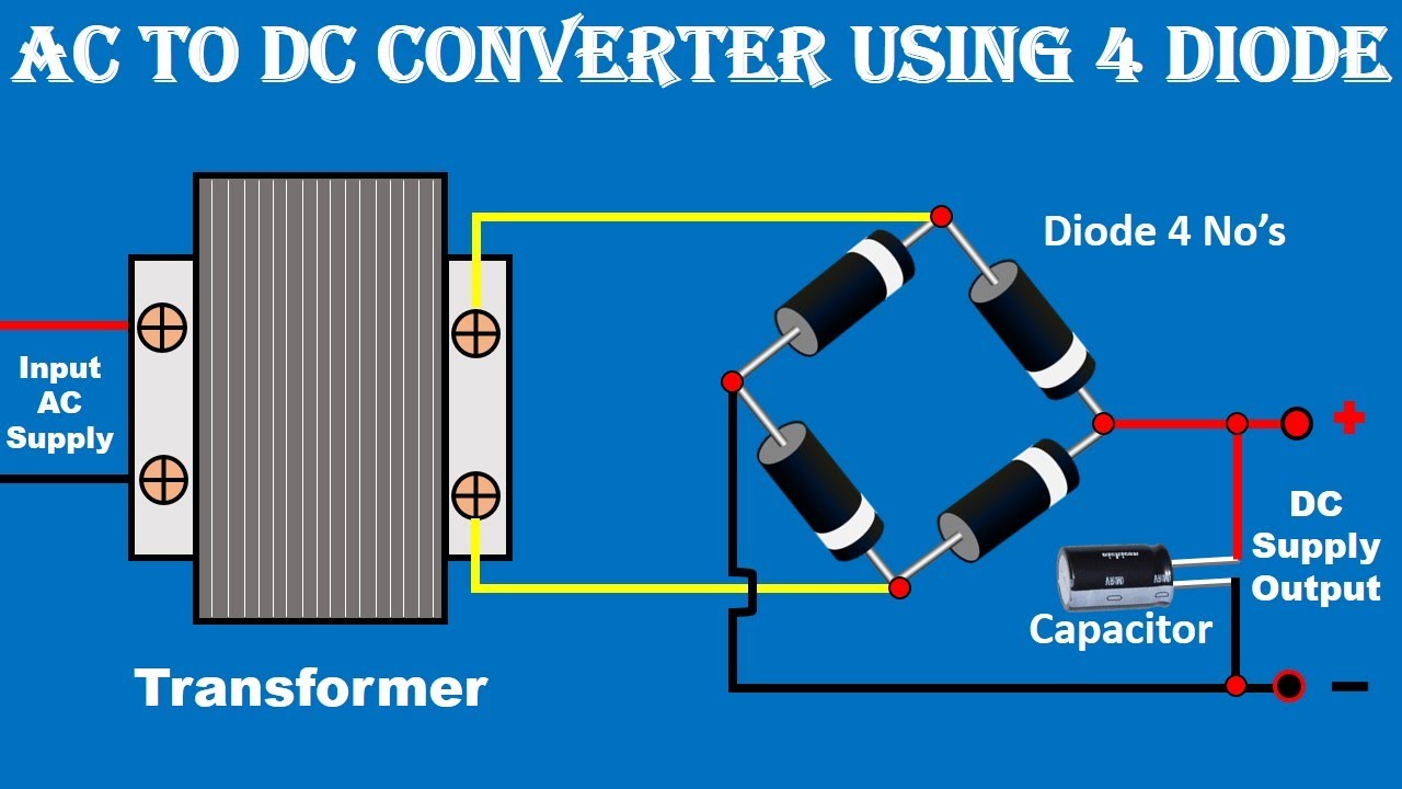
From www.youtube.com
AC to DC Converter Circuit Diagram/with voltage regulator for 12v A To D Converter Circuit Diagram Also called the parallel a/d converter, this circuit is the simplest to understand. It is an electronic device used for converting an analog signal into a digital signal. It is formed of a series of comparators, each. we describe here four major circuit architectures used in a/d converter (adc) design and outline the role they play in. adc. A To D Converter Circuit Diagram.
From wirepartnotaryship.z22.web.core.windows.net
Analog To Digital Circuit Diagram A To D Converter Circuit Diagram adc stands for analog to digital converter. It is formed of a series of comparators, each. It is an electronic device used for converting an analog signal into a digital signal. we describe here four major circuit architectures used in a/d converter (adc) design and outline the role they play in. Also called the parallel a/d converter, this. A To D Converter Circuit Diagram.
From electricalnotebook.com
Implementation of D/A Converter Free Electrical Notebook Theory and A To D Converter Circuit Diagram we describe here four major circuit architectures used in a/d converter (adc) design and outline the role they play in. adc stands for analog to digital converter. It is formed of a series of comparators, each. It is an electronic device used for converting an analog signal into a digital signal. Also called the parallel a/d converter, this. A To D Converter Circuit Diagram.
From wiringbiotaxismopa33c.z21.web.core.windows.net
A/d Converter Circuit Diagram A To D Converter Circuit Diagram Also called the parallel a/d converter, this circuit is the simplest to understand. we describe here four major circuit architectures used in a/d converter (adc) design and outline the role they play in. adc stands for analog to digital converter. It is formed of a series of comparators, each. analog to digital converter (adc) is an electronic. A To D Converter Circuit Diagram.
From circuitdatamorwenstow.z21.web.core.windows.net
12 Volt Ac To Dc Converter Circuit Diagram A To D Converter Circuit Diagram we describe here four major circuit architectures used in a/d converter (adc) design and outline the role they play in. It is an electronic device used for converting an analog signal into a digital signal. It is formed of a series of comparators, each. Also called the parallel a/d converter, this circuit is the simplest to understand. adc. A To D Converter Circuit Diagram.
From wirepartnotaryship.z22.web.core.windows.net
Simple Dc To Dc Converter Circuit Diagram A To D Converter Circuit Diagram It is an electronic device used for converting an analog signal into a digital signal. It is formed of a series of comparators, each. analog to digital converter (adc) is an electronic integrated circuit used to convert the analog signals such as voltages to digital or. Also called the parallel a/d converter, this circuit is the simplest to understand.. A To D Converter Circuit Diagram.
From www.seekic.com
Microporoer_12_bit_A_D_converter AD_DA_Converter_Circuit Circuit A To D Converter Circuit Diagram analog to digital converter (adc) is an electronic integrated circuit used to convert the analog signals such as voltages to digital or. Also called the parallel a/d converter, this circuit is the simplest to understand. It is formed of a series of comparators, each. It is an electronic device used for converting an analog signal into a digital signal.. A To D Converter Circuit Diagram.
From www.researchgate.net
shows the block diagram of a conventional flash A/D converter with A To D Converter Circuit Diagram analog to digital converter (adc) is an electronic integrated circuit used to convert the analog signals such as voltages to digital or. It is formed of a series of comparators, each. adc stands for analog to digital converter. It is an electronic device used for converting an analog signal into a digital signal. we describe here four. A To D Converter Circuit Diagram.
From guidefixneryoriescemiaq.z4.web.core.windows.net
Design Of Ac To Dc Converter A To D Converter Circuit Diagram It is an electronic device used for converting an analog signal into a digital signal. analog to digital converter (adc) is an electronic integrated circuit used to convert the analog signals such as voltages to digital or. It is formed of a series of comparators, each. Also called the parallel a/d converter, this circuit is the simplest to understand.. A To D Converter Circuit Diagram.
From howelectrical.com
What is DC to DC Boost Converter? Working Principle, Waveforms, Circuit A To D Converter Circuit Diagram we describe here four major circuit architectures used in a/d converter (adc) design and outline the role they play in. It is formed of a series of comparators, each. Also called the parallel a/d converter, this circuit is the simplest to understand. adc stands for analog to digital converter. analog to digital converter (adc) is an electronic. A To D Converter Circuit Diagram.
From enginedatasatisfy.z13.web.core.windows.net
A/d Converter Circuit Diagram A To D Converter Circuit Diagram analog to digital converter (adc) is an electronic integrated circuit used to convert the analog signals such as voltages to digital or. It is an electronic device used for converting an analog signal into a digital signal. adc stands for analog to digital converter. we describe here four major circuit architectures used in a/d converter (adc) design. A To D Converter Circuit Diagram.
From schematiclechfaniq.z4.web.core.windows.net
Simple Dc Dc Converter Circuit Diagram A To D Converter Circuit Diagram Also called the parallel a/d converter, this circuit is the simplest to understand. It is an electronic device used for converting an analog signal into a digital signal. adc stands for analog to digital converter. we describe here four major circuit architectures used in a/d converter (adc) design and outline the role they play in. analog to. A To D Converter Circuit Diagram.
From guidelistgordon.z6.web.core.windows.net
A/d Converter Circuit Diagram A To D Converter Circuit Diagram we describe here four major circuit architectures used in a/d converter (adc) design and outline the role they play in. It is an electronic device used for converting an analog signal into a digital signal. It is formed of a series of comparators, each. adc stands for analog to digital converter. Also called the parallel a/d converter, this. A To D Converter Circuit Diagram.
From www.researchgate.net
A/D converter block diagram. Download Scientific Diagram A To D Converter Circuit Diagram we describe here four major circuit architectures used in a/d converter (adc) design and outline the role they play in. It is formed of a series of comparators, each. adc stands for analog to digital converter. analog to digital converter (adc) is an electronic integrated circuit used to convert the analog signals such as voltages to digital. A To D Converter Circuit Diagram.
From www.researchgate.net
Basic block diagram of the AtoD converter at higher frequencies A To D Converter Circuit Diagram we describe here four major circuit architectures used in a/d converter (adc) design and outline the role they play in. analog to digital converter (adc) is an electronic integrated circuit used to convert the analog signals such as voltages to digital or. adc stands for analog to digital converter. It is an electronic device used for converting. A To D Converter Circuit Diagram.